

| Home | |
Forschung | |
Prozessmikroskop | |
Bilder | |
|
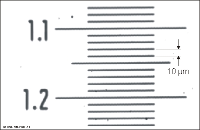
Figure 1.Section cut from the image of a millimeter scale, obtained with the 'cold' microscope, using the 11x lens. The spacing of the lines is 10µm. The lines are well resolved, indicating that the resolution in this microscope image is at least of the order of 2 µm. |
|
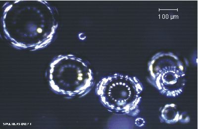
Figure 2.Image of air bubbles in water, obtained with the 'cold' immersion microscope, using the 11x lens. The bubbles act as perfect little convex mirrors, reflecting the illuminating light. It can be seen that this light comes from 18 distinct sources (from the 18 fibers). |
|
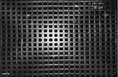
Figure 3.Image of a metal mesh structure with a periodicity of 100 µm. This picture shows that there is essen-tially no image distortion, and that the illumination is not uniform. By the focussing action of the axicon lens, the available illumination energy is concentrated into a central region of 600 µm diameter. This improves the imaging of weakly scattering particles, e.g. cells in water. |

|
Figure 4.Image of colourless transparent crystals (ascorbic acid, C6H8O6 ) suspended in water by stirring. The smallest crystals have a size of ~ 30 µm. This picture illustrates the imaging of moving objects (velocity v ~ 1 m/s). The motion is 'frozen' by the flash illumination (t ~ 3 µs). The resulting motion blur is ~ 3 µm and hardly discernible in this picture. |
|
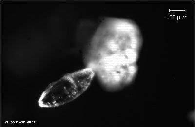
Figure 5.Another picture of a crystal of ascorbic acid in water. This view gives an imression of the 3rd dimension: The crystal to the left happens to be 'in focus', another object to the right (another crystal ?) is in the background and appears diffuse due to 'defocusing'. |
|
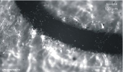
Figure 6.Example of a still 'dry' image, obtained with the microscope in air: The surface of white paper, with part of a letter printed by a laser printer. The fibrous structure of the paper and individual grains of the black 'toner' can be distinguished. The printed line has a width of ~ 170 µm. |
|
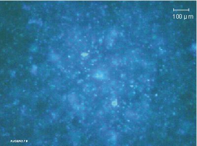
Figure 7.Image of nearly transparent algae (pseudo Kirchneriella subcapitata) suspended in water, illuminated by the flash lamp through a blue filter, (lc ~ 455 nm), observed without filtering. The smallest discernible cells are ~ 2...3 µm in size. This picture illustrates the possibilty of regognizing cells selectively by their fluores-cence. (see Figure below) |
|
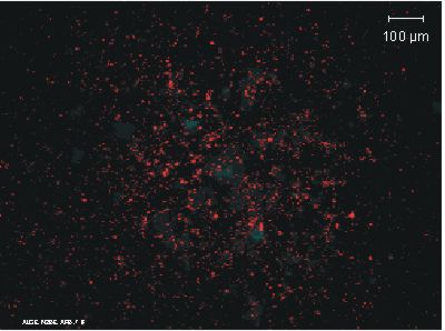
Figure 8.Illustration of 'fluorescence imaging': The same scene as above, illuminated through a blue filter (blocking red light), and observed through a red filter (blocking the blue illuminating light). The fine dots visible in this image appear intensely red. They represent red fluores-cent light, generated in the cells under excitation by the blue illuminating light. The fluorescent cells are estimated to be <= 2 µm in size. |
|
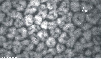
Figure 9.Grains of corundum, Al2O3 (surface of abrasive paper), with an average particle size of ~ 100 µm. The dough-nut-like appearance of the particles is an artifact, resulting from the dark-field illumination. |
 Home
Home |
 pakendorf@tu-harburg.de
 |